If You’re Welder You Must Know how to read welding blueprints to Understand welding diagrams. First, need to know Basic Welding Symbols Pictures, and meaning. In this article, we try to explain Some basic weld symbols and what’s their use. For welders, it is essential to be capable of interpreting or understanding the symbols of welding accurately. It permits them to generate good quality work in a short time. Correctly reading different blueprints has different benefits. It saves time and costs by correctly completing projects and the first attempt without wasting time—unfortunately, many welders have difficulty reading blueprints.
In the market, multiple welders don’t take vocational training. Some welders have attended classes, but they don’t get familiar or trained regarding blueprints, or some welders do not give attention to written stuff. These consequences are that several welders effectively know about the blueprints and read them accurately or effectively use these blueprints in their workplace.
Welding Companies Role For Welding Blueprint Adoption
It should be stated that different companies of welding have a significant role in welding blueprint adoption. Only a few companies restricted their welder to must know about symbols and read them correctly. In the market, there is a deficiency of good welders. Multiple companies are unwilling to impose difficult conditions for hiring new welders as these welders are not feasible. The company employs those welders who are not efficient in reading different blueprints, but it doesn’t mean that company cannot train these welders to get better. Training sessions are conducted by welding companies for their hired welders to enhance welders’ technical skills. Within the organization, coaching classes for welders can be conducted, and they could also spread awareness by attaching posters in the work area with different welding symbols.
One issue faced by multiple welding manufacturers is that they don’t have a trainer in the company who could train welders to read different blueprints or drawings. Such type of issues occurs in small and medium-sized organizations. If your company needs this type of training, then you must hire support from external sources through welding trainers, which are professional. Vendors are supplied by welding, especially manufacturers of welding equipment and wholesale distributor, attains this knowledge. Always offer a training session by the company to their hired employees.
Welding Blueprints Fundamentals
The individual will review the basic welding blueprints. In particular areas, different symbols of welding are available. These symbols highlight the kind of work that should be conducted to finish the project of welding. Various symbols have different meanings. Let’s have a look.
How to Read Welding Symbols on Blueprints
Using a particular structure, the welding symbols are drawn that explain the type and direction of the weld. Each symbol of welding that individuals see must have an arrowhead this points to that location or position where individuals require to do the weld.
![]()
This arrow is connected to a line which is called a leader line. With additional lines, this leader line intersects that horizontally run. The arrow could point downwards or upwards, identifying where the welder does the weld.
Finally, at the reference line opposite end, a tail is available. The tail might have fewer forks that basically point off in various directions. For weld, specialized instructions are suggested by this tail. Welders need to understand and interpret accurately different welding symbols.
![]()
If we have a review at the reference line center, you would see either geometric or parallel lines. Such type of lines identifies the weld type that you require to create on different metal frames.
There are multiple kinds of welds that you could make. To perform the job accurately, it is not essential to become confused among the weld symbols. Different symbols are available on reference lines that identify the weld type that must be done during all welding symbols that provides you complete and accurate instructions for the welding project.
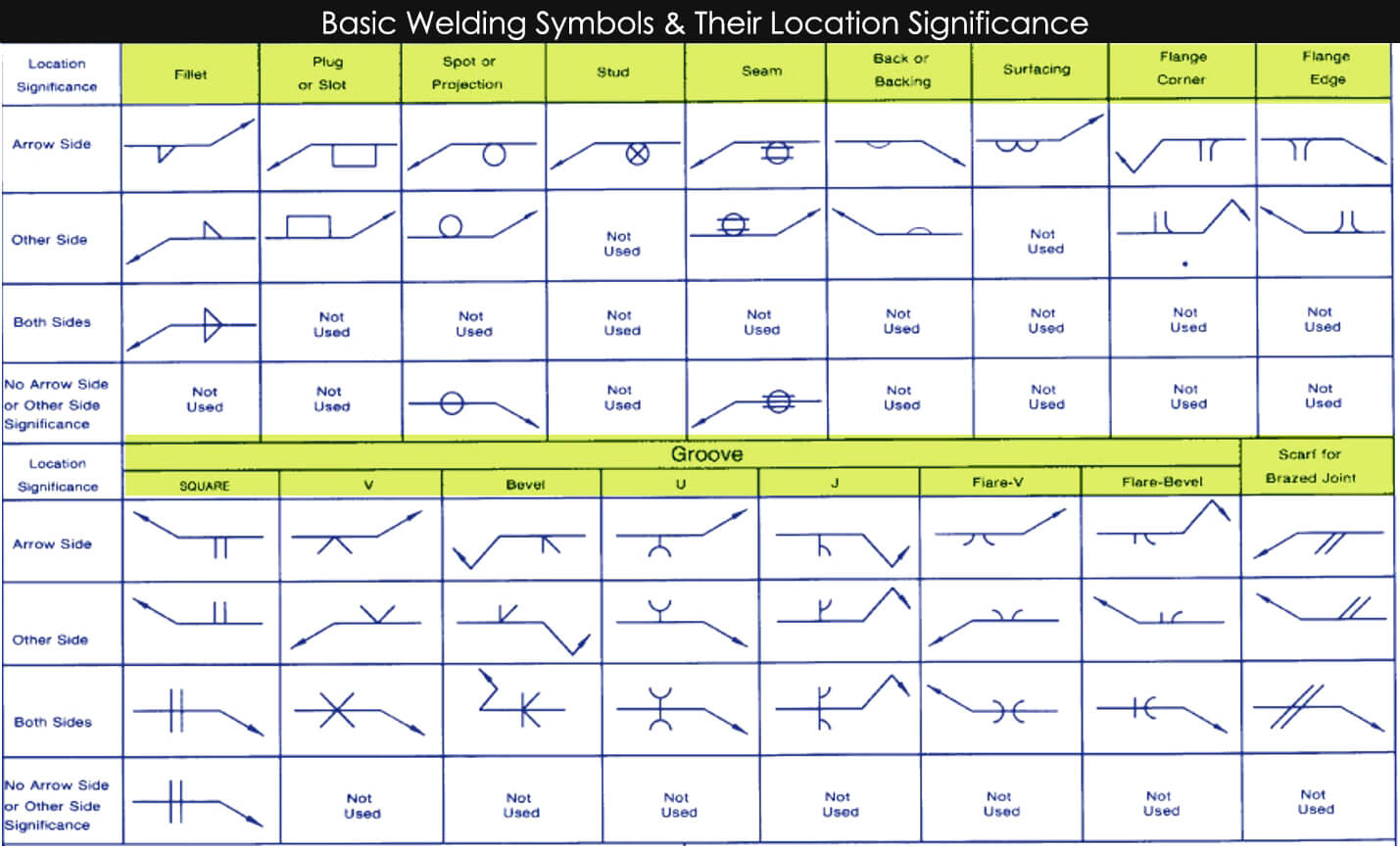
When welders read welding diagrams or sketches, they pay more attention to symbol placement on the reference line. Suppose that weld symbols are available below that reference line, then weld must be conducted on the joint arrow side. Whereas if the different symbol of the weld is available on the reference line top as shown in the diagram, the weld must be conducted on the opposite joint side from which direction arrow is basically pointing.
According to observation, if different symbols of the weld are present on the reference line both sides, then many welds should be built on joints both sides. Various symbols of weld have been built to distinguished among the kinds of welds that you could utilize on your work or project. The symbol, which is “||” shaped points toward the square weld, whereas s “V” means V weld must be used.

There are many symbols; for learning and memorizing these symbols, welders need some time. They must be able to distinguish among these symbols. The easy way to printout these basic symbols then attach these printouts on the welder; this makes things more accessible for people to recognize and interpret. Once people have memorized and learned the basic symbols, they can learn more additional symbols, which are not common.
Basic weld symbols Picture
Letters Written on Welding Symbols
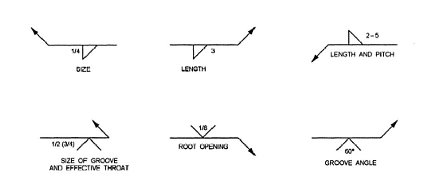
Individuals read welding blueprints then he/she must be able to find several letters on charts. Such letters represent to individual a piece of essential information to note when doing the welds, like root openings & length. Some reference is given below for different letters.
- C denotes a Chipping Finish
- F represents a Finish Symbol
- G denotes a Grinding Finish
- L: denotes the Weld length
- M denotes a Machining Finish
- R denotes a Root Opening
- T denotes a Specification Process
As mentioned above, these letters are viewed along with the welding symbol if a particular weld is available that should be acted to finish the entire project.
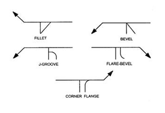
Common Symbols
Many cryptic symbols are used in blueprints of welding for indicating the weld. Such symbols support the welder in interpreting size & processing and finishing information for the entire project. In this part, we will review several common symbols that are used. Through the ANSI, people can seek the complete symbols set for welding.
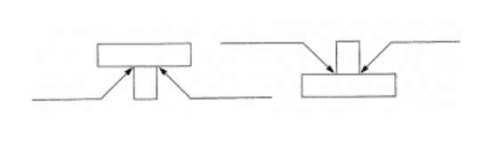
Filler Welds
Generally, the fillet weld is used to create the lap joints of 90-degree, corner joints, and T-joints. If we see the symbol, it represents that at the cross-section, the weld is triangular. The shape isn’t the same as a triangle of 90 degrees & there could be several changes to weld. A little quantity of metal used for welding is deposited; 2 members create the collaborative. It fuses & penetrates with frame stuff to create a joint.

The perpendicular leg of the triangle is drawn on the symbol left side, irrespective of weld orientation. The leg size is written on the weld symbol left side. Let’s suppose that both legs of the weld are of the same size; then, the symbol would represent one-dimension solely. Let’s consider if both legs have different sizes. As a result, both dimensions would be provided. The drawing would also observe that which leg is assumed to be too long.
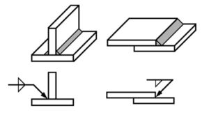
Groove Welds
Generally, groove weld is used to build joints attached among the edges of 2 various metal sheets or frames. It can be seen in the diagram that is mentioned above. In multiple ways, groove weld could be created. In corner joints, joints, or T joints, this kind of weld can also be used among flat and curve metal pieces. In welding, difference relies on different parts shape that is combined & the procedure of how these shapes are created at edges.

In the welding procedure, within the groove, joining metal basically deposited as it fuses & penetrates with metal on various sheets to build the joint. There are multiple categories in which groove weld could be categorized which are the following:
Square Groove
This groove type is created by forming a slight metal edge parting or tight fit among two metal frames. The space diameter is created using this procedure if any symbol is represented on the weld symbol.

For different plug welds, each plug diameter is seen on the symbol left side. The plug’s pitch is written on the right side. For each particular slot, width is utilized in different slot welds, labeled on the symbol left side, whereas the pitch and length are written on the symbol right side.
Basic Blueprint Reading For Welders:
Conclusion
The conclusion drawn from the above discussion is that the welder life is usually meant to follow a particular blueprints collection. In the market, multiple welders don’t take vocational training. If any welder doesn’t have much knowledge regarding welder blueprints, welders’ opportunities might become limited in this particular field. Be an efficient and excellent welder.
The welder must have the ability to interpret and understand the different welding blueprints. A particular point, there are several varying welding symbols. Such type of symbols identifies what kind of work should be done to accomplish the entire project. The welders must be familiar with the majority of symbols; these symbols will help them in work.